Design of the Raspberry Pi Radio
In this installment I will try and outline the main components that take part in the Raspberry Pi radio.
Of course the most significant part is the Raspberry Pi. This is responsible for the actual radio playback, streaming down and so on. But there are some other components that make it all possible.
Hardware
One of my requirements was to use the existing controls on the radio. I wanted to use the existing volume control (a potentiometer), the on/off switch and the channel selection controls. In the future I may bring more and more radio controls into play.
On the left hand side, there is a band selection knob. This was used to switch between SW bands, 6 of them. I wanted to use this as a channel selection control.
 |
| SW Band Selection - also volume control in view |
 |
| 19m to 49m, short waves |
When I examined the channel selector, I realised that I could represent the 6 states it has by using 3 bit digital inputs.
The second input I wanted to use was the On/Off button at the front of the radio. Rather than cutting the power supply, this will now function like a mute button. The circuits are not being shut down but this will stop the playback (and more).
 |
| The On Off Switch |
So I have the following controls available to me:
- An On/Off (Ein/Aus) switch
- A 10K Potentiometer for Volume
- The channel selection knob.
The On/Off is another single bit digital input.
I decided to A/D sample the volume control to control the actual volume of the radio. Later I will explain the attractiveness of this.
In order to achieve all of these objectives, I decided to use an Arduino Uno development board. Arduino is an excellent open source microcontroller development system. The microcontroller is Atmel AVR. More details can be found here: http://arduino.cc/en/
The board I used has sufficient I/O pins to input the channel selection, on/off switch and an A/D input for volume control.
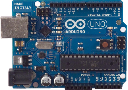 |
| Arduino Uno - very much recommended |
The next hurdle was to connect the Ardunio to the Raspberry Pi. Both systems support the I2C protocol. I2C protocol is a serial two wire protocol which allows different chips talk to each other over short distances. Arduino platform supports I2C and Raspberry Pi supports that too, with some tweaks.
The main problem on the I2C front was the voltage levels. The IO pins of Raspberry Pi operate with 3.3V logic. The Ardiuno works on 5V. If I tried to connect them directly, that would most definitely fry the Raspberry Pi.
So I used a bi-directional level shifter. This is a very simple but very clever piece of circuit that can translate the logic levels of the systems back and forth.
You can make your own bi-directional level shifter but that might require eyeballs size of watermelons. The surface mounting tiny components were too small for me to work with so I actually purchased one that was made by some robot.
It was clear that I needed an audio power amplifier. Raspberry Pi has an audio output jack but that would not be able to drive a loudspeaker. So I decided to build a simple audio power amplifier. I used an LM386; a very popular low power audio amplifier. That, again, worked pretty well without much effort.
 |
| LM386 - It works |
Finally, I designed a power supply to power the entire system using mains without any need for any power adaptors and so on.
Here is a view of the built radio:

Software
OK, I am using the official Raspberry Pi Raspbian as the Operating System.
First and foremost I needed a radio player program. The excellent Media Player Daemon (MPD) is an excellent choice. This supports a very large number of formats. Because it is a Linux daemon it runs in the background and you can write programs (MPD clients) to control the playback, playlists.
http://mpd.wikia.com/wiki/Music_Player_Daemon_Wiki
So I wrote a C++ program, the radio controller, which talks to Arduino on the I2C protocol and controls the MPD using the MPD protocol. MPD Protocol is a socket/text based protocol.
Typically, my program reads the inputs from the radio controller, such as volume level, channel selection and convert these to commands to issue to the Media Player Daemon. So when I twist the channel selection, this translates to a digital input to the Arduino and this is then picked up by my radio controller software and this issues the correct playlist control commands to MPD.
MPD starts up when the Raspberry Pi boots up and so does my radio controller program.
Great work, thanks for sharing it.
ReplyDeleteThis is exactly the kind of project that I was looking for to play with my PI.
Quick question, why involve both the arduino & the rasberry-pi? Couldn't the gpio on the PI do it all?
Hi,
ReplyDeleteSorry about the late reply. In the simplest terms, the GPIO would not be able to Analog-Digital conversion. Cheers HC
I like the idea to simultaneously using Raspberry AND Arduino ! Well done.
ReplyDelete