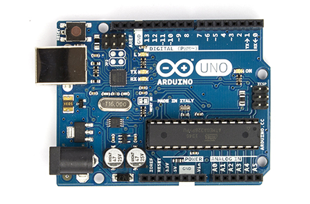
Arduino is an open source hardware/software platform based on the Atmel AVR micro controllers.
My Arduino is of the Uno model:
My radio has an on/off button, a volume control pot and a channel selector (SW band selector). I have designated these as inputs to the Arduino. Then my program running on the micro processor reads the inputs and also communicated with the Raspberry Pi.
The link between the Arduino and the Raspberry Pi is based on the I2C protocol, as I explained in my previous post. The Arduino software library, http://arduino.cc/en/Reference/Libraries, contains calls for communicating using I2C protocol. In this configuration, Raspberry Pi is the master and Arduino is the slave. That is, Raspberry Pi always initiates the communication link.
As per I2C, Raspberry Pi sends the address of my Arduino program on the hardware interface and the Arduino library allows me to respond to this reqeuest and send some data back.
So the role of the Arduino program is to continuously gather data from the radio controls, volume, on/off switch etc, and provide their state to the Raspberry Pi whenever a request is made.
I am including the code for the Arduino at this site on Source Forge
https://sourceforge.net/projects/r-pi-radio/files/
There, Arduino.zip contains the C++ code that runs on the Arduino.
Notable details:
There is a data structure called HardwareState which represents the data made available from all sensors on the radio. I have split the volume control value to two bytes. Also the cookie Low and High contain my initials. This data structure is updated every 10ms.
class HardwareState
{
private :
unsigned char m_size;
unsigned char m_onOff;
unsigned char m_channelValue;
unsigned char m_volumeLow;
unsigned char m_volumeHigh;
unsigned char m_cookieLow;
unsigned char m_cookieHigh;
When the I2C master (the Raspberry Pi) requests data, the data structure is sent on the I2C bus:
void onI2cRequest()
{
Wire.write((unsigned char*)&state, sizeof(state));
lastConnect = masterConnected;
}
There is also an output pin which is connected to a transistor which switches a bright white LED that is used to illuminate the radio display. If the I2C master does not connect for more than a second, the Arduino program assumes that the Raspberry Pi is not active and blinks the LED as a visual clue to the user. For example, when powered up for the first time, the LED starts blinking until Linux boots up and starts running the program on the Raspberry Pi.

Excellent project! I found your site while searching on I2c and arduino, and I found your post quite fascinating. Keep up the good work and keep writing for people like me to read.
ReplyDeleteThanks :)
Delete